
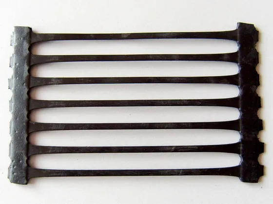
 Geogrid
 Uniaxial Geogrid
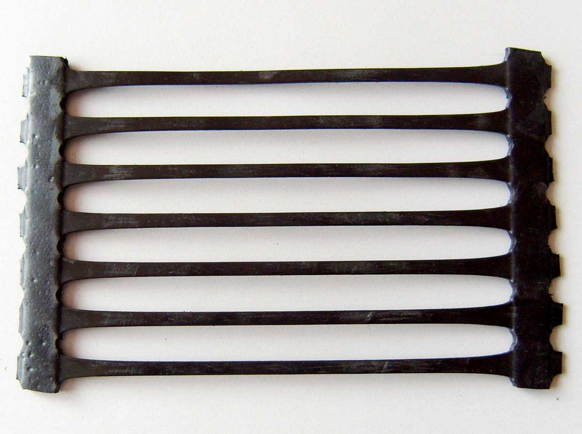
PP and HDPE uniaxial geogrid for retaining walls, MSE walls and reinforced slopes — 60–300 kN/m machine-direction strength, long oval apertures, low creep.
- 60–300 kN/m
- PP · HDPE uniaxial
- ASTM D6637
A geogrid reinforced retaining wall works as a mass, not as a face. The mechanism, why uniaxial grid is the workhorse, the installation sequence step by step, and the mistakes that bring walls down.
A block or panel face on its own is a stack of units resisting earth pressure by weight alone, and above a fairly modest height it loses. Building a retaining wall with geogrid changes the structure completely: horizontal layers of grid are laid into the compacted backfill and connected at the facing, so the face, the reinforcement and the soil between them act as one coherent block. Each layer is in tension, pulling the face back into a mass of soil far heavier than the face itself. The wall then resists overturning and sliding as a gravity structure whose weight is the reinforced soil, not the blocks. The same principle governs a segmental retaining wall, an MSE wall behind precast panels and a reinforced bridge abutment fill — only the facing differs.
The load pattern in a reinforced soil mass runs one way: every layer pulls back, perpendicular to the face. Uniaxial geogrid is punched and then drawn in the machine direction alone, which aligns the polymer along that pull and opens the holes into long oval apertures. The result carries very high tension along the roll with little elongation and little long-term creep, and only nominal load across it — exactly the anisotropy the structure wants. A biaxial grid spends half its polymer on a direction the wall does not load. Where the wall is tall or the design life long, a knitted polyester geogrid is the other main option: it is flexible, develops high force at low strain, and publishes long-term design strength against a stated design life, which is what a submittal for a major structure has to show.
Layer spacing, embedment length behind the failure plane, the required long-term design strength per layer, connection capacity at the facing and the backfill specification are all outputs of a wall design. They follow from the wall height, the backfill friction angle, groundwater, surcharge and the facing system, and they change layer by layer up the same wall — spacing typically tightens toward the base where earth pressure is highest. There is no rule of thumb that survives contact with a real site, and any supplier who hands you a spacing before seeing the design is guessing with your wall. We supply the grade and geometry the design calls for, and we will say plainly when a question belongs to the design engineer. What follows is construction practice, which is a different thing from design.
Geogrid retaining wall installation follows the same order on every job. 1) Excavate and prepare the reinforced zone, and build the levelling pad and first facing course dead level — everything above inherits that line. 2) Place and compact backfill to the level of the first reinforcement layer shown on the drawings. 3) Roll the grid out with the machine direction running back into the fill, perpendicular to the face, and connect or lap it at the facing course so the layer lands on a block joint. 4) Pull it hand-taut to remove waves and stake it back; never stretch a layer to correct alignment. 5) Backfill over the grid to the length the drawings show, spreading forward off already-placed material rather than tracking on the exposed grid, and compact in the specified lift thickness — using hand equipment within the compaction-exclusion zone near the face so the blocks are not shoved out of line. 6) Repeat to the top, then cap and complete the drainage. Keep rolls covered before they are buried.
Four failures account for most of what goes wrong on a geogrid wall. Too few layers, or the wrong grade — usually the result of value-engineering the reinforcement after the design was signed off, or copying a layout from a shorter wall. Grid cut short, so it does not extend past the potential failure surface into stable ground; a layer that stops early is not a layer. Poor compaction, particularly of the fill immediately over each grid, because the reinforcement only mobilises through friction and interlock with dense soil, and loose fill lets the face bulge. Drainage left out, which is the quiet one: water building up behind a wall adds a pressure the design never accounted for and softens the very fill the reinforcement relies on. Every one of these is invisible once the wall is finished.
Drainage is part of the structure, not an accessory. A wall needs a drainage layer behind the facing and a route out at the base, and it needs the reinforced fill kept apart from the retained soil so fines do not migrate in and clog it. A nonwoven geotextile is the usual filter and separator between the drainage stone and the surrounding soil; a woven geotextile is used where the separation layer must also carry load. Where space behind the face is tight, a geonet drainage core gives a high-flow path in a fraction of the thickness of a stone drain. Sizing all of this — chimney or blanket drain, outlet spacing, filter criteria — again belongs to the designer.
Take away the hard facing and the same reinforcement lets a fill slope stand far steeper than its soil friction angle would allow — that is geogrid slope stabilization, and it buys back footprint on a constrained site. Layers are built into each lift and often wrapped at the face, with a surface treatment holding the topsoil while vegetation establishes. Specifying geogrid for slopes follows the same discipline as a wall: layer geometry from the stability analysis, compaction achieved lift by lift, and drainage designed rather than assumed. Send us the design long-term strength, the layer layout and the total area and we will quote against it; the geogrid range and the geotextiles that go with it are on our products page.
Free Geosynthetics Spec & Selection Guide
Material grades, thickness/GSM sizing and price ranges for your project — sent to your inbox.
It ties the facing to the soil behind it. Horizontal layers laid into the compacted backfill and connected at the face put that soil into a reinforced block, so the wall resists overturning and sliding as one heavy mass instead of as a stack of units. The grid works in tension; the soil supplies the weight and the friction that anchors it.
That is set by the wall design, not by a general rule. Vertical spacing, embedment length and the required strength per layer come out of an analysis of the wall height, backfill properties, groundwater, surcharge and facing system, and they vary up the height of the same wall. In practice layers are tied to the facing course height so each lands on a block joint. Build to the drawings, and have an engineer produce them.
Far enough past the potential failure surface to be anchored in stable ground, which is a design output based on wall height, backfill strength and surcharge — not a fixed multiple you can apply blind. Embedment cut short on site is one of the most common causes of movement in reinforced walls, so the layer length on the drawings is not somewhere to save material.
Uniaxial. Reinforcement in a wall is loaded in one direction — back into the fill, perpendicular to the face — and a uniaxial grid concentrates its strength along exactly that axis. Biaxial geogrid is drawn both ways for areas loaded from every direction, which is why it belongs under roads, yards and working platforms rather than behind a wall face.
Always. Reinforcement does nothing about water. Pressure building up behind the wall is a load the design did not allow for, and saturated fill loses the strength the grid depends on. A drainage layer behind the facing, a filter fabric or geonet to keep it from clogging, and a positive outlet at the base are part of the structure — leaving them out is one of the classic ways a well-reinforced wall still fails.
Not for anything of consequence. Wall height, surcharge, slope above and below, groundwater and backfill quality all change the required reinforcement, and most jurisdictions require a designed and permitted wall above a modest height. We supply the grade and geometry a design specifies and can advise on product selection and installation practice, but we do not set layer spacing, lengths or strengths for someone else's wall.
Geogrid PP and HDPE uniaxial geogrid for retaining walls, MSE walls and reinforced slopes — 60–300 kN/m machine-direction strength, long oval apertures, low creep.
 Geogrid
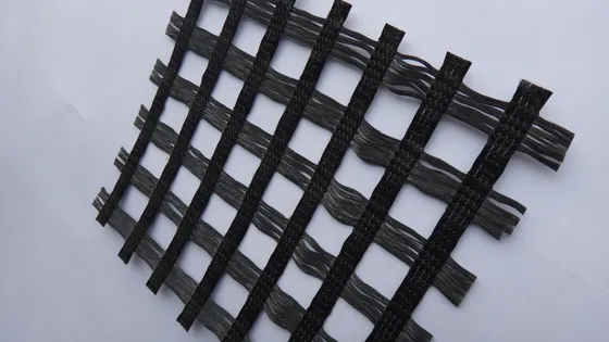
 Warp-knitted PET geogrid with published long-term design strength — 34 to 452 kN/m LTDS at a 120-year design life, PVC, SBR or bitumen coated.
 Geotextile
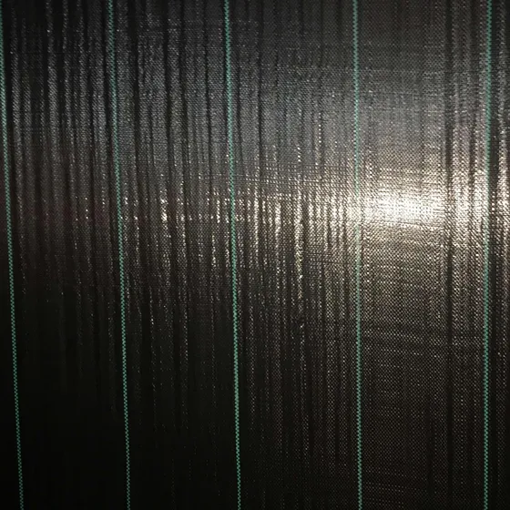
 High-strength woven geotextile fabric (PP / PET high-tenacity yarn) to AASHTO M288 — for separation, stabilization and reinforcement on roads.
 Geotextile
 Needle-punched nonwoven geotextile fabric (PET / PP staple fiber) to AASHTO M288 — for filtration, separation, drainage and protection in French drains.
 Erosion Control
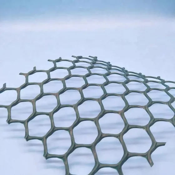
 HDPE plastic flat mesh (geonet) — extruded polyethylene netting in 7 models, 550–1240 g/m², for slope protection, fencing and ground reinforcement.
Tell us your application and quantity — our English-speaking team replies within one business day.